Gustavus Adolphus College’s Experimental Wind Amplifying System
Based on Invelox by Sheerwind in Chaska, MN
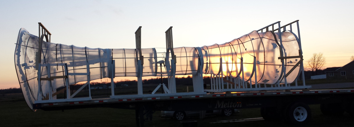
The setting sun through the shrink wrap. Photo by Bradley Niederriter
Watch this space for Data Releases and Video Streams
A New Wind Delivery System - Jill Malecha, Ben Rorem, Rochelle Widmer, and Chuck Niederriter
Jill Malecha, Rochelle Widmer and Chuck Niederriter proposed to build and characterize a new wind delivery system as a student/faculty research collaboration. Ben Rorem joined the group as a First Year Research Experience (FYRE) student and has been intimately involved in the project from the beginning. Jill had another summer internship but took over for Rochelle when she began her study away program in Scotland in September.
Approximately six years ago, Daryoush Allaei, invented a new "wind delivery system" that brings wind down to ground level and speeds it up in a venturi where the energy is extracted via a smaller wind turbine. Dr. Allaei founded Sheerwind Incorporated to develop and promote the system, but up until now very few systems have actually been constructed so there is limited real data to compare to simulations done by faculty and students at the University of Minnesota and City College of New York.
In late May Ben and Rochelle began characterizing the 400 W Sunforce wind turbine that had been purchased for the project. They also analyzed data from several weather stations on campus to determine the most prominent wind speed and direction. These data and the use of COMSOL simulation software allowed them to work together with Sheerwind engineers to design the linear wind accelerating system, shown below. It should be noted that budgetary constraints dictated the near ground linear design. Their project is to construct and instrument a small demonstration system on the Gustavus campus so that further research can be done by Gustavus students.
 The geometry of the wind accelerating system. The Venturi diameter was determined by the turbine diameter and intake and diffuser size by ratio of the predominant incoming wind speed and plateau in the turbine power curve. The system is being constructed with a 2.3 m intake diameter, venturi diameter of 1.2 m, diffuser diameter of 3.1 m and total length of 10.8 m.
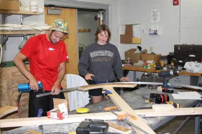
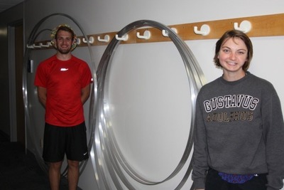
After developing the design, Ben and Rochelle needed to determine the best approach for implementation of the design and construction of the system. To keep cost down, they chose construct the entire system from aluminum rings and industrial heat shrink wrap. They constructed jigs to bend the 1” wide aluminum into rings of the appropriate diameter and subsequently bent and riveted all of the rings needed. Examples of their work are shown below.
 |
 |
Ben prepares to rivet one of the larger rings as Rochelle maintains its curvature. |
Rochelle and Ben with some of the rings they made. |
The venturi section of the system is small enough that it could be constructed inside Olin Hall, while the intake and diffuser sections were built outside by Jill and Ben. Figure 4 illustrates the ring and shrink wrap construction, as well as the turbine mount. At the time the picture was taken, the turbine was still mounted on the roof of Olin Hall for continued data collection.
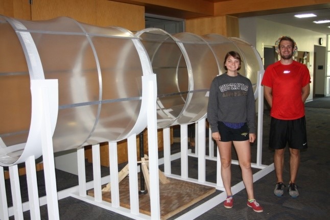 Rochelle and Ben with the venturi section of the system. The open section where the turbine will be installed will be closed in by hard plastic for safety.
In addition to constructing the wind accelerating system, Ben and Rochelle spent a good deal of time determining the best way to instrument the system to collect accurate data on wind speeds and power generated. After the failure of a commercial data logging system purchased for another project, they designed and built an Arduino minicomputer based system to collect data. Unidirectional and omnidirectional wind speed meters will be installed in all three sections of the system to allow comparison to the fluid flow simulations done in COMSOL. The power generated by the turbine will be used to charge a bank of 12 volt batteries and the amount of power measured and compared to predicted values.
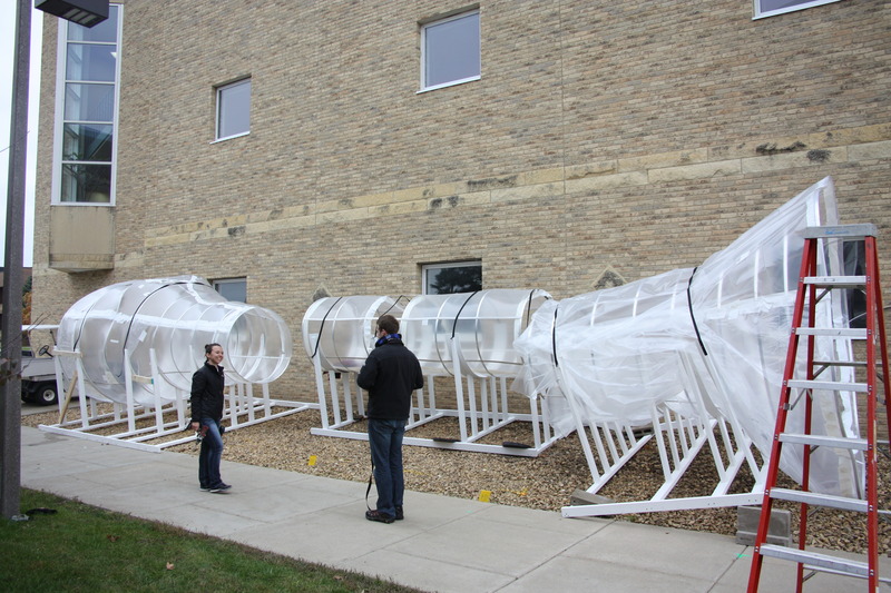 Jill and Ben Discuss How the System Will Fit Together.
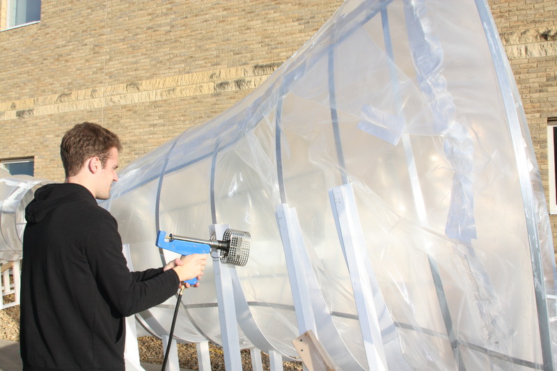
Ben Heats the Shrink Wrap Carefully to Avoid Burning Holes In It. Note: This Is Easier When It Isn’t Windy.
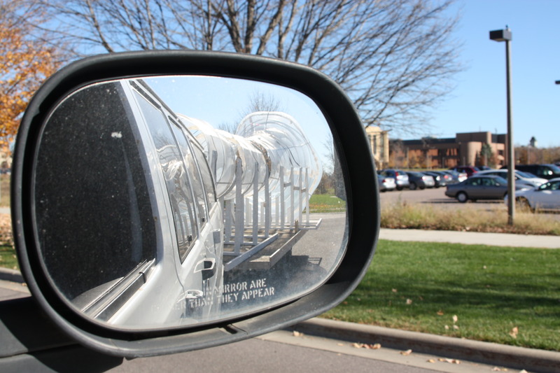
Transporting the Diffuser and Center Sections on Facilities’ Snowmobile Trailer.
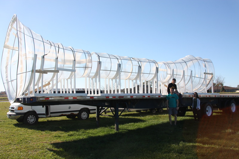
Ian McKeag, Ben, and Jill Are Happy That All of the Pieces Made it to the Trailer Intact.
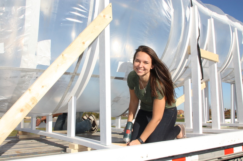
Jill Secures the Support System to the Trailer.
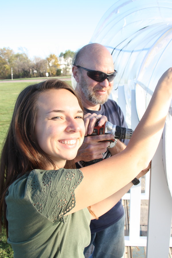
Jill and Chuck Install the Straps to Hold the System in Place. These Were Supplemented by Wooden Supports to Minimize Shifting.
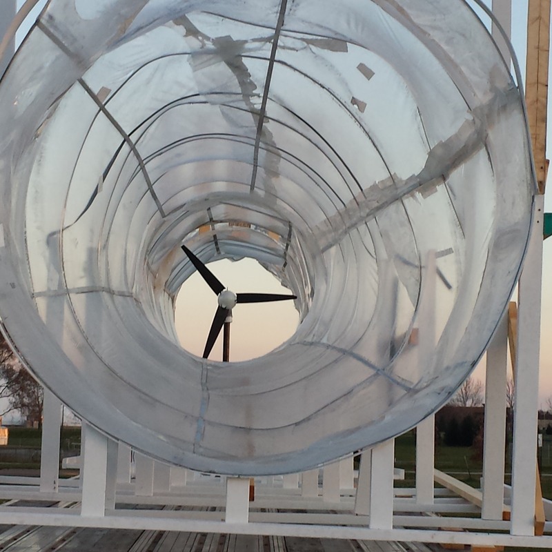 Looking toward the turbine from the condenser end. Photo by Bradley Niederriter
