File list
This special page shows all uploaded files.
| Date | Name | Thumbnail | Size | Description | Versions |
|---|---|---|---|---|---|
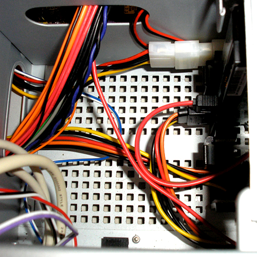
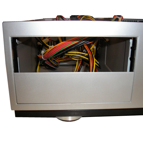
| 23:39, 25 March 2007 | Step28.jpg (file) |  |
127 KB | Step 28: The connections on the back of the case. | 1 |
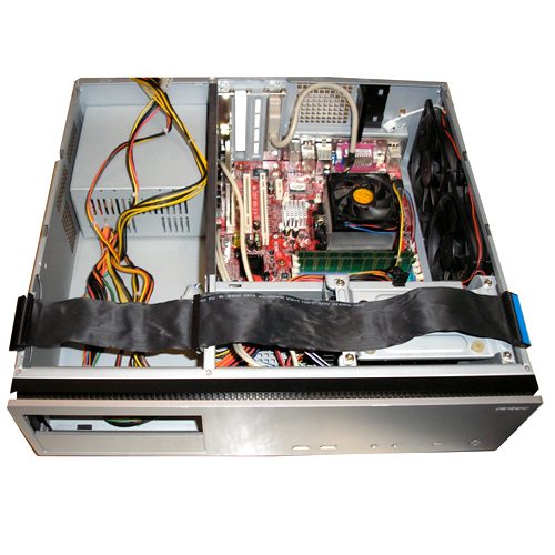
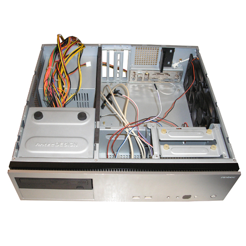
| 23:38, 25 March 2007 | Step27.jpg (file) |  |
110 KB | Step 27: All hardware assembly complete. | 1 |
| 23:37, 25 March 2007 | Step26.jpg (file) |  |
226 KB | Step 26: A tidied-up CD cage area. | 1 |
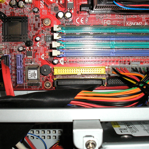
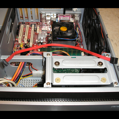
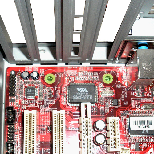
| 23:36, 25 March 2007 | Step25.jpg (file) |  |
392 KB | Step 25: The correct placement of the IDE ribbon cable in the motherboard. | 1 |
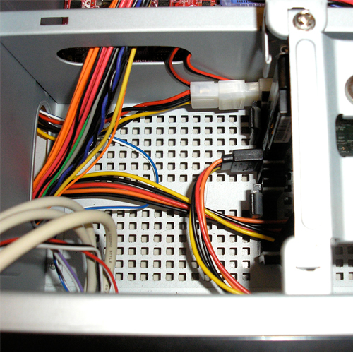
| 23:35, 25 March 2007 | Step24.5.jpg (file) |  |
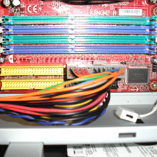
249 KB | Step 24.5: The correct placement of the IDE ribbon cable and 4-pin power cable from the power supply. | 1 |
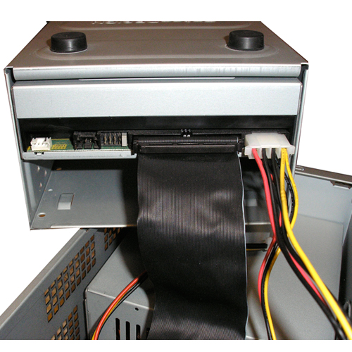
| 23:35, 25 March 2007 | Step24.jpg (file) |  |
231 KB | Step 24: The IDE ribbon cable. | 1 |
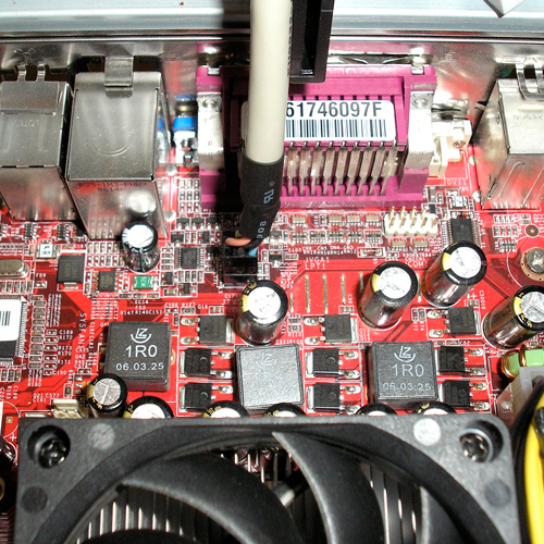
| 23:33, 25 March 2007 | Step23.jpg (file) |  |
388 KB | Step 23: The correct placement of the video out adapter's connector. | 1 |
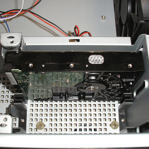
| 23:32, 25 March 2007 | Step22.jpg (file) |  |
380 KB | Step 22: The correct placement of the wireless PCI card. | 1 |
| 23:31, 25 March 2007 | Step21.jpg (file) |  |
322 KB | Step 21: Correct placing of the front panel audio connector. | 1 |
| 23:28, 25 March 2007 | Step20.jpg (file) |  |
331 KB | Step 20: The USB cable connected to the motherboard properly. | 1 |
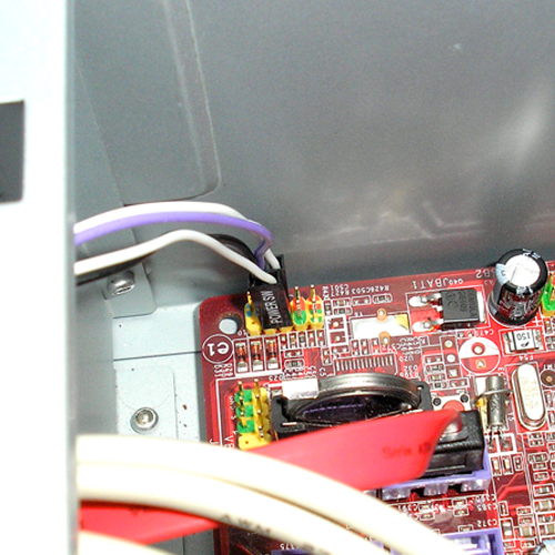
| 23:27, 25 March 2007 | Step19.jpg (file) |  |
268 KB | Step 19: The "Reset SW" and "Power SW" cables connected to the motherboard properly. | 1 |
| 23:27, 25 March 2007 | Step18.jpg (file) |  |
420 KB | Step 18: The remaining front panel cables pulled into the main area. | 1 |
| 23:26, 25 March 2007 | Step17.jpg (file) |  |
291 KB | Step 17: The black tie and power cables neatly tied. | 1 |
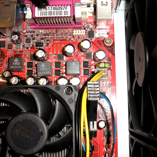
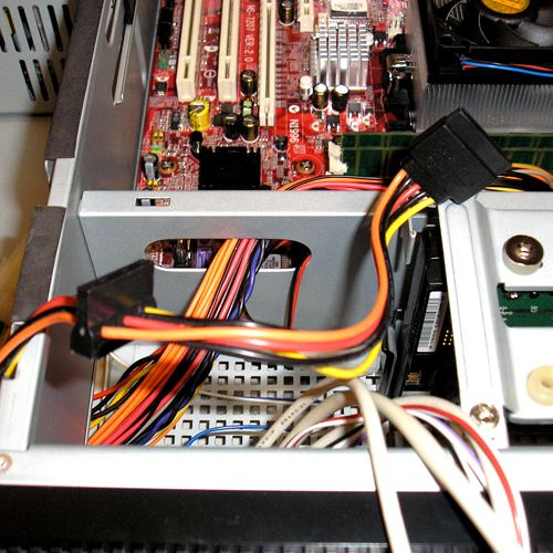
| 22:28, 25 March 2007 | Step16.5.jpg (file) |  |
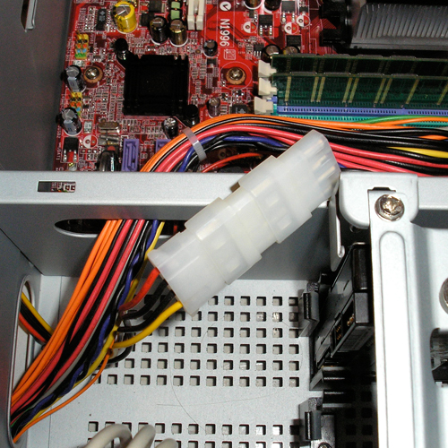
348 KB | Step 16.5: Correct connection and routing of the ATX 4-pin power cable. | 1 |
| 22:27, 25 March 2007 | Step16.jpg (file) |  |
292 KB | Step 16: The ATX 4-pin motherboard power cable. | 1 |
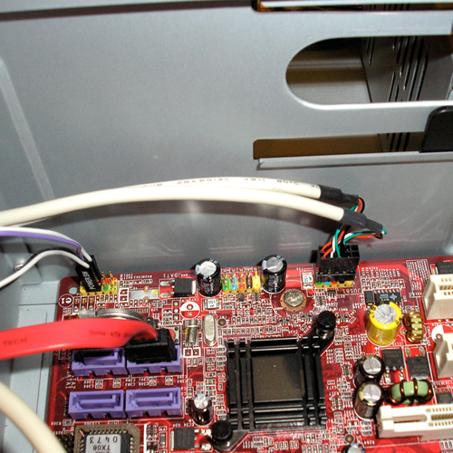
| 22:26, 25 March 2007 | Step15.6.jpg (file) |  |
378 KB | Step 15.6: The Serial ATA cable plugged into the motherboard's top left Serial ATA connector. | 1 |
| 22:26, 25 March 2007 | Step15.5.jpg (file) |  |
337 KB | Step 15.5: The Serial ATA cable routed to the motherboard. | 1 |
| 22:24, 25 March 2007 | Step15.jpg (file) |  |
284 KB | Step 15: The Serial ATA cable. | 1 |
| 22:24, 25 March 2007 | Step14.5.jpg (file) |  |
294 KB | Step 14.5: Correct seating of the Serial ATA power cable in the hard drive. | 1 |
| 22:23, 25 March 2007 | Step14.jpg (file) |  |
347 KB | Step 14: The Serial ATA power cable. | 1 |
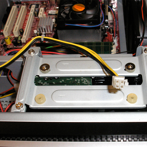
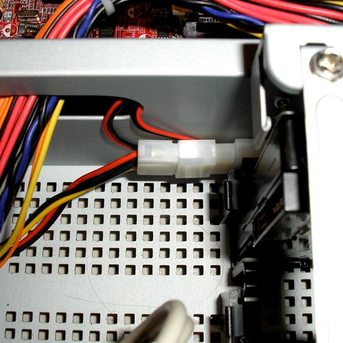
| 22:22, 25 March 2007 | Step13.5.jpg (file) |  |
299 KB | Step 13.5: Proper connection of the blue and white cable to the spare power connector. | 1 |
| 22:21, 25 March 2007 | Step13.jpg (file) |  |
260 KB | Step 13: The blue and white power connector. | 1 |
| 22:20, 25 March 2007 | Step12.5.jpg (file) |  |
288 KB | Step 12.5: Suggested "tuck away" of the fan power connectors. | 1 |
| 22:20, 25 March 2007 | Step12.jpg (file) |  |
333 KB | Step 12: Proper routing and connection of the 4-pin power cable. | 1 |
| 22:19, 25 March 2007 | Step11.5.jpg (file) |  |
305 KB | Step 11.5: Proper fan power cable connection in the drive cage. | 1 |
| 22:18, 25 March 2007 | Step11.jpg (file) |  |
354 KB | Step 11: Proper routing of the fan power cables to the drive cage. | 1 |
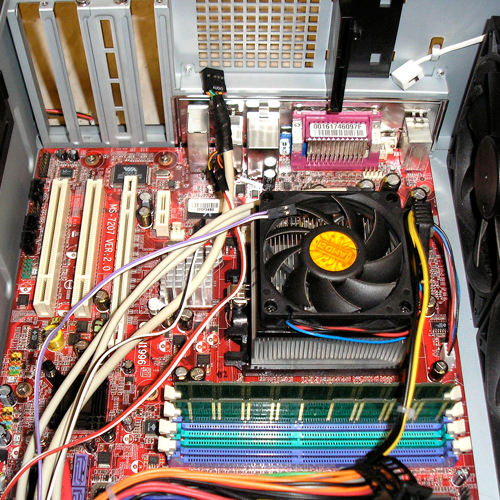
| 22:17, 25 March 2007 | Step10.jpg (file) |  |
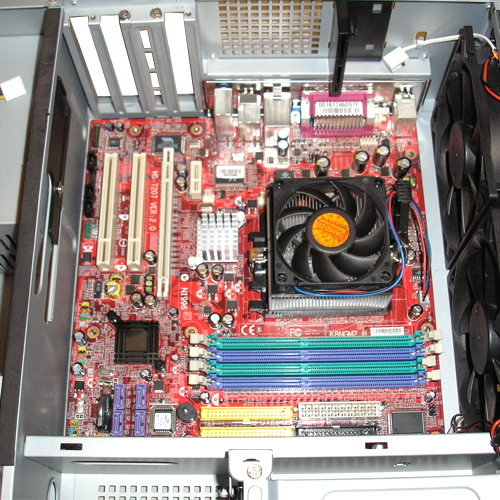
354 KB | Step 10: Proper installation of the memory. | 1 |
| 22:17, 25 March 2007 | Step9.5.jpg (file) |  |
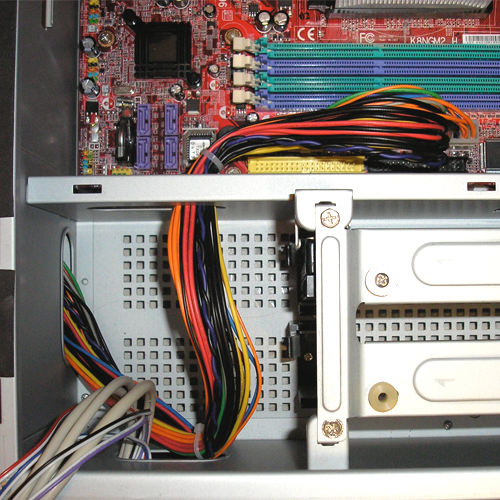
349 KB | Step 9.5: ATX motherboard cable plugged into the motherboard correctly. | 1 |
| 22:16, 25 March 2007 | Step9.jpg (file) |  |
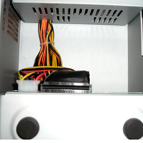
328 KB | Step 9: Proper routing of the ATX motherboard power cable. | 1 |
| 21:17, 25 March 2007 | Step7.5.jpg (file) |  |
352 KB | Step 7.5: Motherboard resting on the brass posts. | 1 |
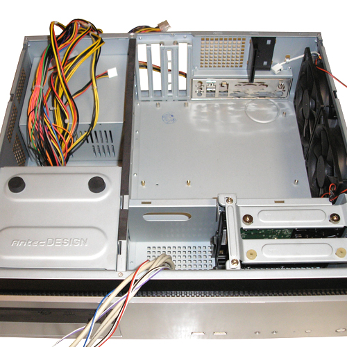
| 21:17, 25 March 2007 | Step7.jpg (file) |  |
269 KB | Step 7: Case with cables cleared out of the main area. | 1 |
| 21:15, 25 March 2007 | Step8.5.jpg (file) |  |
432 KB | Step 8.5: Motherboard mounting holes. | 1 |
| 21:15, 25 March 2007 | Step8.jpg (file) |  |
355 KB | Step 8: Top of the motherboard being lined up with the brass posts. | 1 |
| 20:56, 25 March 2007 | Step6.5.jpg (file) |  |
250 KB | Step 6.5: Drive cage with top back on and hard drive mounted. | 1 |
| 20:56, 25 March 2007 | Step6.jpg (file) |  |
276 KB | Step 6: Drive cage with hard drive placed inside it. | 1 |
| 20:55, 25 March 2007 | Step5.5.jpg (file) |  |
263 KB | Step 5.5: Drive cage with the top removed. | 1 |
| 20:54, 25 March 2007 | Step5.jpg (file) |  |
224 KB | Step 5: Drive cage with screws removed. | 1 |
| 20:41, 25 March 2007 | Step4.jpg (file) |  |
185 KB | Step 4: DVR Case with CD Cage Replaced. | 1 |
| 20:40, 25 March 2007 | Step3.jpg (file) |  |
177 KB | Step 3: Top-most drive bay cover removed. | 1 |
| 20:39, 25 March 2007 | Step2.5.jpg (file) |  |
130 KB | Step 2.5: The proper mounting of the DVD drive in the CD cage. | 1 |
| 20:39, 25 March 2007 | Step2.jpg (file) |  |
119 KB | Step 2: Mounting holes for the DVD drive. | 1 |
| 20:24, 25 March 2007 | Step1.jpg (file) |  |
264 KB | Step 1: CD Drive Cage Removed. | 1 |
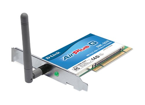
| 20:11, 25 March 2007 | Wirelesscard.jpg (file) |  |
56 KB | The D-Link DWL G510 Wireless PCI Card. | 1 |
| 20:09, 25 March 2007 | Videoout.jpg (file) |  |
44 KB | The Video Out Adapter For The MSI K9NBPM2-FID. | 1 |
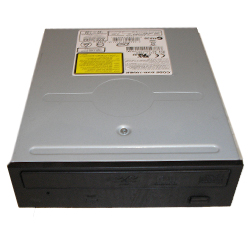
| 20:08, 25 March 2007 | Dvddrive.jpg (file) |  |
67 KB | The Pioneer DVR-112D DVD-RW Drive. | 1 |
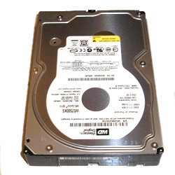
| 20:07, 25 March 2007 | Harddrive.jpg (file) |  |
96 KB | The Western Digital SE 16 250gb Hard Drive. | 1 |
| 20:05, 25 March 2007 | Motherboard.jpg (file) |  |
119 KB | The MSI K9NBPM2-FID Motherboard. | 1 |
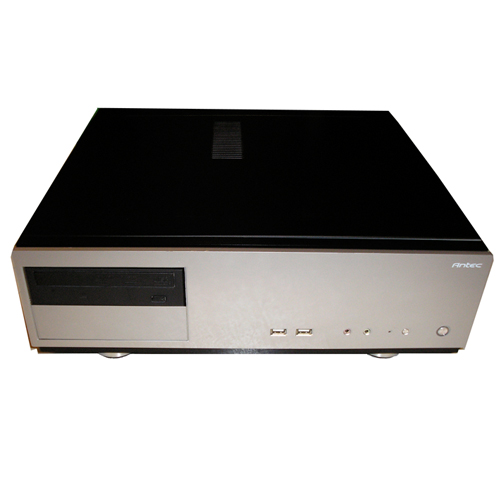
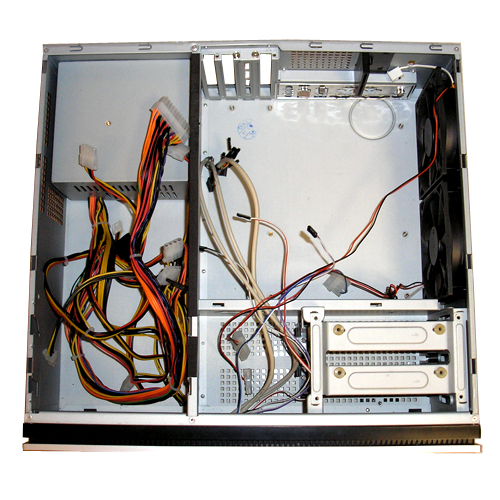
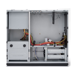
| 20:04, 25 March 2007 | Case.jpg (file) |  |
67 KB | The Inside of The Antec NSK2400. | 1 |
| 17:58, 25 March 2007 | Screwdriver.jpg (file) |  |
42 KB | A Craftsman Phillips Head Screwdriver | 1 |
| 17:50, 25 March 2007 | DWL-G510.jpg (file) |  |
18 KB | The D-Link DWL G510 Wireless PCI Card. | 1 |